SystemHUD
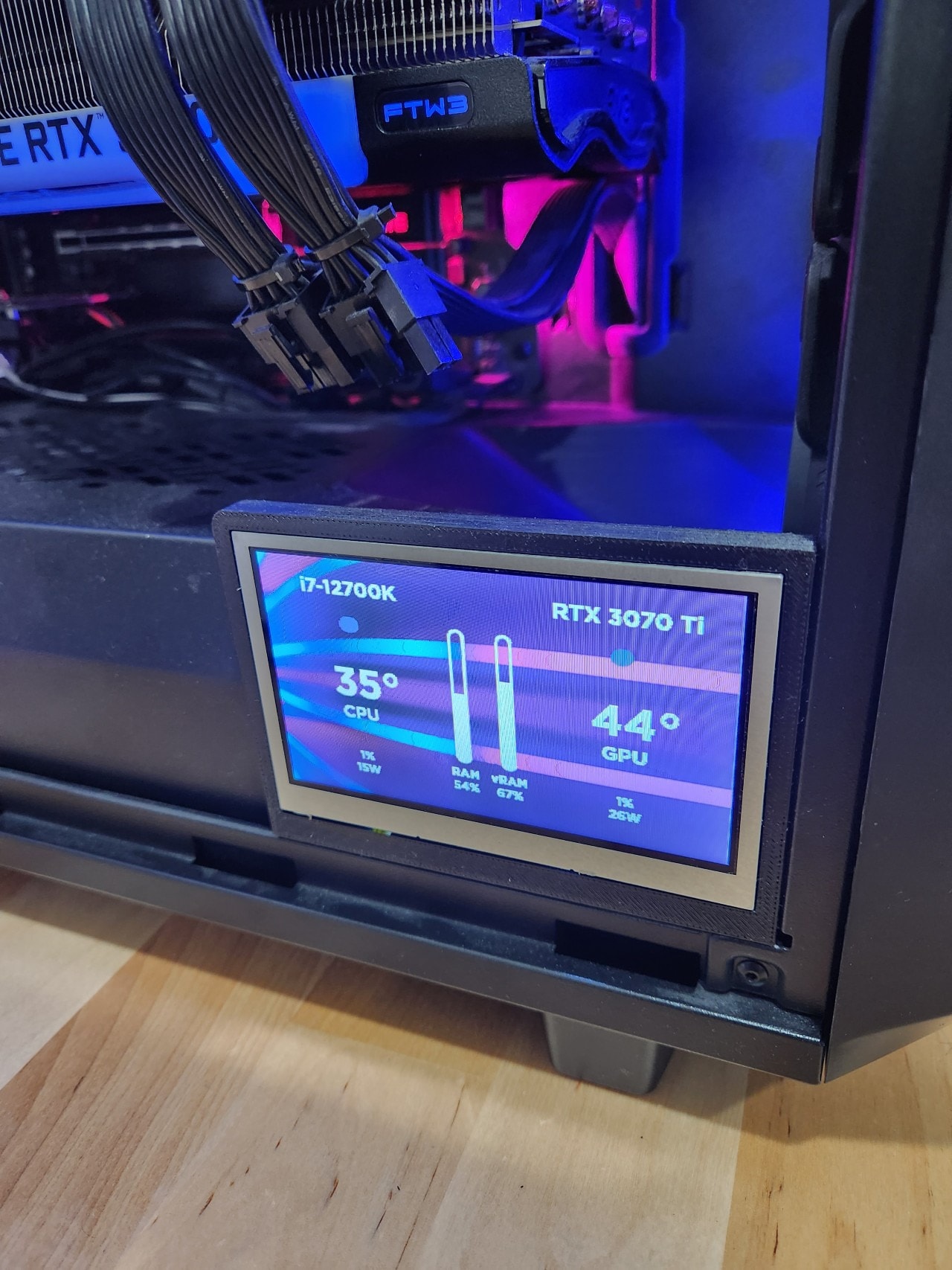
Usually, junk mail is just that: junk, but this time it was a bit more. We received a thick brochure in the mail. This odd brochure had an LCD screen inside it that played a video when the mail was opened. Instead of just throwing it out, I decided to give this horrible waste of money destined to be e-waste a new purpose in life as a small screen in my PC case that can track system information.
Physical Supplies
- 4.3” 40-pin TFT Display - 480x272 (no touch preferred but it will probably still work with it)
- 40-pin FPC Extension Board + 200mm Cable (or buy both separately)
- TFP401 HDMI/DVI Decoder to 40-Pin TTL Breakout - Without Touch
- ~2’ HDMI Cable
- ~2’ USB Micro-B Cable
- Arduino UNO (only needed for reprogramming the EPROM)
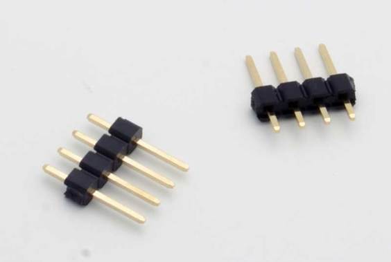
- 1x 4 Pin Jumpers (usually included with Arduino kits)
- 4x Jumper Extension
Software
- Rainmeter + Custom Programmed Skin
- HWINFO
- Fusion 360 or similar CAD software
Step 1: Tearing Down the Brochure
The video mailer I got was similar to the one shown here:

After tearing down the brochure, I recovered this LCD Display:

It is very similar to the one that Adafruit sells with a touchscreen: https://www.adafruit.com/product/1591

Step 2: Initial Testing
First I took the display and put it into the case to find a spot where it fit in and looked good.

The original board allowed me to upload my own video and play it on loop so, of course, I had to do this:

Step 3: Designing an Enclosure
My PC is built in the Fractal Design Meshify 2 Compact Case and so the screen enclosure was made to fit that.


The screen is 3.05 mm thick
On the back of the LCD, I added a spot to house the extension board for the 40-pin ribbon cable
Step 4: Getting the Decoder Ready
Out of the box, the HDMI decoder was not ready to use just yet, there are two things I had to do. First, I had to change the backlight brightness.

There are these two jumpers that can be used to change the backlight current. Mine is probably 50mA so I soldiered the connection across the first one.

This will provide the LCD backlight 25+25=50mA of current.
Next, I had to soldier the pin headers to the EDID EPROM pads.

These pads need to be connected to an Arduino with jumper cables to reprogram the EDID.


Step 5: Reprogramming The EDID EPROM
The EDID is the part of the decoder that tells the computer the size and capabilities of the display connected. By default, it is configured for an 800x480 display. Since mine is 480x272, I used a slightly modified Arduino script from the Adafruit website to change it.
#include <Wire.h> //I2C library

/* 480x272 @ 25mhz */

const uint8_t PROGMEM eepromdat[128] = {
0x00, 0xFF, 0xFF, 0xFF, 0xFF, 0xFF, 0xFF, 0x00, 0x04, 0x81, 0x43, 0x00, 0x01, 0x00, 0x00, 0x00,
0x0C, 0x17, 0x01, 0x03, 0x81, 0x0A, 0x06, 0x78, 0x8A, 0xA5, 0x8E, 0xA6, 0x54, 0x4A, 0x9C, 0x26,
0x12, 0x45, 0x46, 0x00, 0x00, 0x00, 0x01, 0x01, 0x01, 0x01, 0x01, 0x01, 0x01, 0x01, 0x01, 0x01,
0x01, 0x01, 0x01, 0x01, 0x01, 0x01, 0xC4, 0x09, 0xE0, 0x33, 0x10, 0x10, 0x14, 0x10, 0x08, 0x05,
0x4A, 0x00, 0x5F, 0x36, 0x00, 0x00, 0x00, 0x18, 0x00, 0x00, 0x00, 0xFC, 0x00, 0x41, 0x44, 0x41,
0x46, 0x52, 0x55, 0x49, 0x54, 0x20, 0x34, 0x33, 0x20, 0x20, 0x00, 0x00, 0x00, 0x10, 0x00, 0x00,
0x00, 0x00, 0x00, 0x00, 0x00, 0x00, 0x00, 0x00, 0x00, 0x00, 0x00, 0x00, 0x00, 0x00, 0x00, 0x10,
0x00, 0x00, 0x00, 0x00, 0x00, 0x00, 0x00, 0x00, 0x00, 0x00, 0x00, 0x00, 0x00, 0x00, 0x00, 0x42
};

/* Adafruit breakout @ 800x480 !
const uint8_t PROGMEM eepromdat[128] = {
0x00, 0xFF, 0xFF, 0xFF, 0xFF, 0xFF, 0xFF, 0x00, 0x04, 0x81, 0x04, 0x00, 0x01, 0x00, 0x00, 0x00,
0x01, 0x11, 0x01, 0x03, 0x80, 0x0F, 0x0A, 0x00, 0x0A, 0x00, 0x00, 0x00, 0x00, 0x00, 0x00, 0x00,
0x00, 0x00, 0x00, 0x00, 0x00, 0x00, 0x01, 0x01, 0x01, 0x01, 0x01, 0x01, 0x01, 0x01, 0x01, 0x01,
0x01, 0x01, 0x01, 0x01, 0x01, 0x01, 0x80, 0x0C, 0x20, 0x80, 0x30, 0xE0, 0x2D, 0x10, 0x28, 0x30,
0xD3, 0x00, 0x6C, 0x44, 0x00, 0x00, 0x00, 0x18, 0x00, 0x00, 0x00, 0x10, 0x00, 0x00, 0x00, 0x00,
0x00, 0x00, 0x00, 0x00, 0x00, 0x00, 0x00, 0x00, 0x00, 0x00, 0x00, 0x00, 0x00, 0x10, 0x00, 0x00,
0x00, 0x00, 0x00, 0x00, 0x00, 0x00, 0x00, 0x00, 0x00, 0x00, 0x00, 0x00, 0x00, 0x00, 0x00, 0x10,
0x00, 0x00, 0x00, 0x00, 0x00, 0x00, 0x00, 0x00, 0x00, 0x00, 0x00, 0x00, 0x00, 0x00, 0x00, 0x17,
};
*/

// I2C eeprom dumper
byte i2c_eeprom_read_byte(uint8_t deviceaddress, uint16_t eeaddress );

#define EEPROMSIZE 256UL  // 0.5 Kb
#define ADDRESS_SIZE 8

byte i2c_eeprom_read_byte(uint8_t deviceaddress, uint16_t eeaddress ) {
    byte rdata = 0xFF;
#if (ADDRESS_SIZE == 16)
    Wire.beginTransmission(deviceaddress);
    Wire.write((eeaddress >> 8)); // MSB
#else
    //deviceaddress |= (eeaddress >> 8);
    Wire.beginTransmission(deviceaddress); // MSB
#endif
    Wire.write(eeaddress); // LSB
    Wire.endTransmission();
    Wire.requestFrom(deviceaddress, (uint8_t)1);
    while (!Wire.available());
    rdata = Wire.read();
    return rdata;
}

void i2c_eeprom_write_byte(uint8_t deviceaddress, uint16_t eeaddress, byte data ) {
#if (ADDRESS_SIZE == 16)
    Wire.beginTransmission(deviceaddress);
    Wire.write((eeaddress >> 8)); // MSB
#else
    //deviceaddress |= (eeaddress >> 8);
    Wire.beginTransmission(deviceaddress); // MSB
#endif
    Wire.write((byte)eeaddress); // LSB
    Wire.write((byte)data);
    Wire.endTransmission();
}

void setup() {
  Wire.begin(); // initialise the connection
  Serial.begin(9600);
  Serial.println(F("EEPROM WRITER"));
  Serial.print(F("EEPROM data size: "));
  Serial.println(sizeof(eepromdat));
  Serial.println(F("Hit any key & return to start"));
  while (!Serial.available());
  byte b;
  Serial.println("Starting");
  for (uint16_t addr = 0; addr < EEPROMSIZE; addr++) {
    if (addr < sizeof(eepromdat)) {
      b = pgm_read_byte(eepromdat+addr);
    } else {
      b = 0xFF;
    }
     i2c_eeprom_write_byte(0x50, addr, b);
     delay(5);
     if ((addr % 32) == 0)
       Serial.println();
     Serial.print("0x");
     if (b < 0x10) Serial.print('0');
     Serial.print(b, HEX); //print content to serial port
     Serial.print(", ");
  }
  Serial.println("\n\r========\n\rFinished!");
  for (uint16_t addr = 0; addr < EEPROMSIZE; addr++) {
    if (addr < sizeof(eepromdat)) {
      b = pgm_read_byte(eepromdat+addr);
    } else {
      b = 0xFF;
    }
    uint8_t d =  i2c_eeprom_read_byte(0x50, addr);
    if ((addr % 32) == 0)
      Serial.println();
    Serial.print("0x");
    if (d < 0x10) Serial.print('0');
    Serial.print(d, HEX); //print content to serial port
    Serial.print(", ");

    if (b != d) {
       Serial.print(F("verification failed at 0x")); Serial.println(addr);
       while (1);
     }
  }
  Serial.println(F("\n\r\n\rVerified!"));
}

void loop() {
}
Step 6: Creating The Rainmeter Skin
I created a Rainmeter skin from the ground up to show my system vitals in a clean, modern UI.


[Extra Side Project]
The bottom fan on the front blows air into the cable “basement” where it does nothing and is wasted. To solve this, I created a part that directs air into the bottom of the GPU to improve cooling by a slight amount.


Final Remarks
Transforming e-waste into a super useful HUD for my PC was a fun experience and taught me a lot about modern electronics while researching how the HDMI signal works and how to make it work with the 40-pin LCD cable.
Resources
- https://www.autodesk.com/education/edu-software/overview?sorting=featured&filters=individual - Fusion 360 free for education
- https://www.youtube.com/c/ProductDesignOnline - Very valuable Fusion 360 lessons
- https://twitter.com/Foone/status/1361889389303930882 - Shares the process of taking apart the mailer; helped me find a working HDMI controller
- https://learn.adafruit.com/adafruit-tfp401-hdmi-slash-dvi-decoder-to-40-pin-ttl-display/overview - Tutorial to set up and use the HDMI controller